Before we consider the question of how to connect a three-phase electric meter with our own hands, we will make a reservation that this is more complicated with three-phase meters than with single-phase meters, where the connection scheme is, in principle, unambiguous.
The connection scheme of a three-phase meter depends on its type. In any case, three-phase meters support single-phase measurement.
There are 4 types of three phase meters
Types of 3 phase meters--> Types of 3 phase meters
These are devices:
- Direct inclusion (also called direct inclusion)
- Indirect inclusion
- Semi-indirect inclusion
- Reactive energy metering
Accordingly, they have different connection methods, we consider them in order.
Three Phase Live Switch
Devices of this type are connected to the network directly, as they are designed for a relatively small throughput capacity, up to 60 kW (respectively, current up to 100 A). It is simply not possible to connect a live electricity meter to a power exceeding that indicated in the passport, since their input and output pads are designed for cross-section of connected wires of 16 or 25 mm.
Connection of a three-phase direct connection meter--> Connection of a three-phase direct connection meter
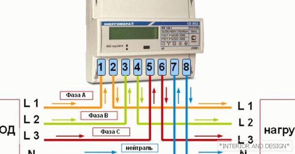
The connection diagram of the live meter, as well as for single-phase meters, except for the passport, is indicated on the back of the cover.
http://moydomik.net/uploads/posts/2017-05/1494931992_shema-podklyuchenia-trehfaznogo-schetchika-prjmogo-vkl.png Connection diagram for direct connection meter--> Connection diagram for direct connection meter
Wires, from left to right:
- The first is the phase A input
- The second - phase A load
- Third — Phase B Input
- Fourth - Phase B load
- Fifth - phase C input
- Sixth - phase C load
- Seventh - zero input
- Eighth - zero load
As you can see, there is no difficulty here.
Semi-indirect switch
These are electricity metering devices that are focused on measuring power consumption in excess of 60 kW. Use is possible only in conjunction with a current transformer, and the connection is carried out according to four schemes.
The digitization of the metering device here is different from the instrument of direct (direct) inclusion.
Connection diagram - wires, from left to right:
- input current winding phase a
- input winding measuring voltage phase A
- phase A current output
- input current winding phase
- input winding measuring voltage phase B
- phase B current output
- input current winding phase C
- input winding measuring voltage phase C
- phase C current winding output
- neutral
- neutral
Consider the contacts of current transformers. There are four of them:
- L1 - power line input
- L2 - power line load
- I1 - meter input winding input
- I2 - meter measuring winding output
Contacts L1 and L2 are always connected to the power network.
When using current transformers, the meter readings are multiplied by the transformation ratio. The intertesting period of a current transformer is 4-5 years.
Connection diagrams for semi-indirect inserts
There are several ways to connect:
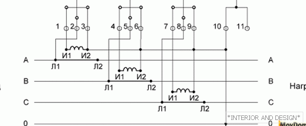
Desyatiprovodnaya counter circuit connection
This circuit is good because here the current and voltage measuring circuits are not interconnected, which increases its electrical safety. However, it requires more wires than other circuits.
http://moydomik.net/uploads/posts/2017-05/1494931353_shema-podklyuchenia-trehfaznogo-schetchika-10-provod-vkl.png Desyatiprovodnaya counter circuit connection--> Desyatiprovodnaya counter circuit connection
Sequence:
- Pin 2 connects to L1 phase A
- Pin 3 is connected to I2 phase A
- Pin 4 connects to phase I1 B
- Pin 5 is connected to L1 phase B
- Pin 6 is connected to the I2 phase B
- Pin 7 is connected to phase I1 C
- Pin 8 is connected to L1 phase C
- Pin 9 is connected to the I2 phase C
- Pin 10 is connected to the neutral wire
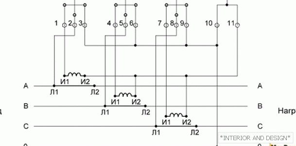
Circuit with connection of current transformers in a star
Allows you to save on the installation of secondary wires.
http://moydomik.net/uploads/posts/2017-05/1494931326_shema-podklyuchenia-trehfaznogo-schetchika-v-zvezdu.png Circuit with connection of current transformers in a star--> Circuit with connection of current transformers in a star
The sequence of execution:
- Contacts 3, 6, 9 and 10 are closed together and connected to the neutral wire
- All contacts I2 are closed between themselves and to contact 11
- Pin 1 is connected to the I1 phase A
- Pin 4 connects to phase I1 B
- Pin 7 is connected to phase I1 C
- Pin 2 connects to L1 phase A
- Pin 5 is connected to L1 phase B
- Pin 8 is connected to L1 phase C
Connection of the meter with combined current and voltage circuits
This scheme is outdated because it is electronic safe, and is not used today.
Connection of the meter through the test terminal box
In essence, it repeats a ten-wire connection scheme, only in the gap between the electric meter and the rest of the elements, an adapter box is installed, which allows you to safely remove and install the metering device.
Indirect Power Counters
Such meters are used to record electricity consumption at voltages above 6kV, so we will not consider them here.
Reactive Energy Counters
By way of connection, they do not differ from active energy metering devices. Although there are still induction meters that take into account the reactive component separately, they are no longer installed at the present time.
In the following articles we will look at the devices of various companies, try to deal with their strengths and weaknesses, if possible, to identify the best brands of electricity meters.


